Analysis of Dual-Pump Combination System for Mine Tailings Discharge
I. System Background and Requirements
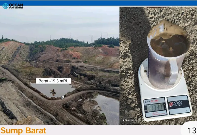
Mine tailings usually contain large amounts of solid particles such as slag and sediment, and the discharge pit is deep (ranging from tens to hundreds of meters). The traditional single-pump system faces two major challenges:
- Inadequate head: It is difficult to directly lift tailings from deep pits to the ground discharge point.
- Severe wear: High-concentration tailings slurry causes intense wear on the pump impeller and casing, making single-pump long-term operation prone to failure.
Therefore, the dual-pump combination system solves the problem of efficient and stable discharge of deep-pit tailings through a relay mode of "pumping + discharging".
II. Core Structure and Working Principle of the Dual-Pump Combination System
(A) System Composition
| Pump Type | Functional Positioning | Typical Model Examples | Core Materials |
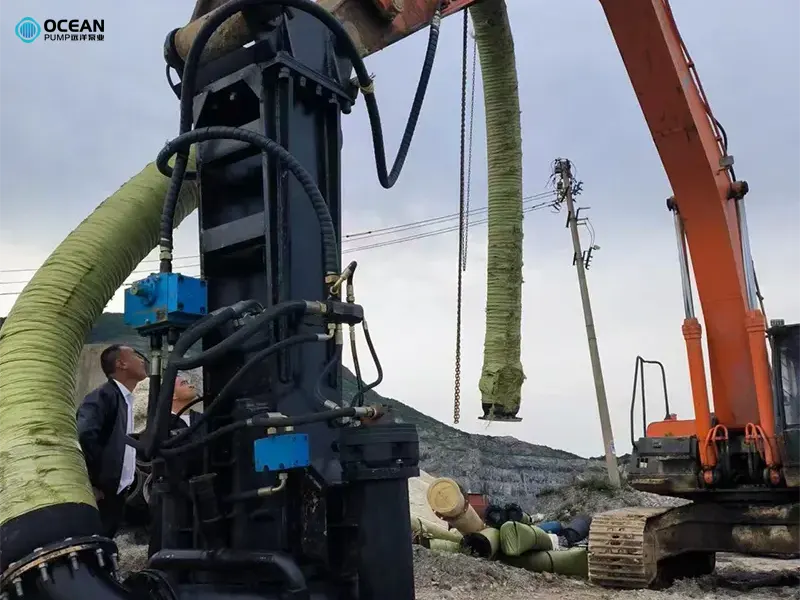
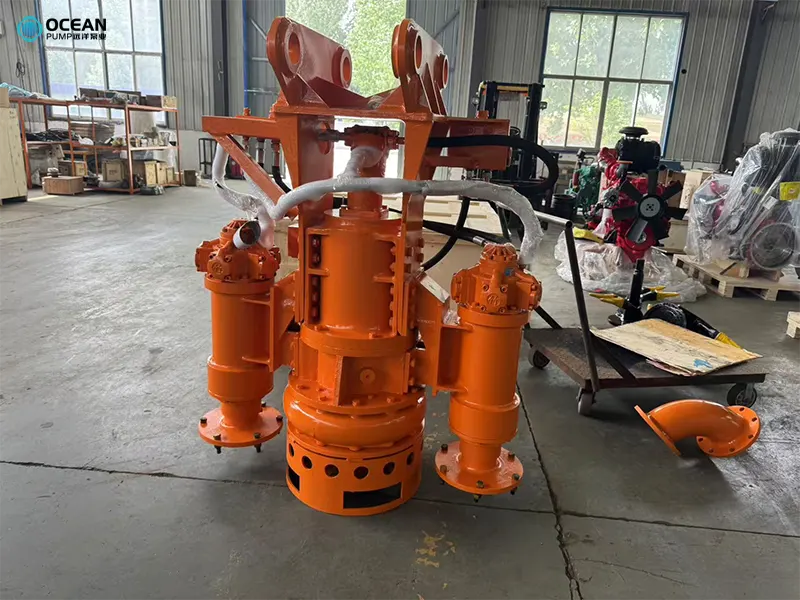
| Pumping Pump (Primary Pump) | Extracts tailings slurry from the bottom of the deep pit and lifts it to an intermediate buffer pool or transition pipeline | Slurry pumps (excavator dredge pump or electricity submersible dredge pump) | High-chromium cast iron, wear-resistant rubber |
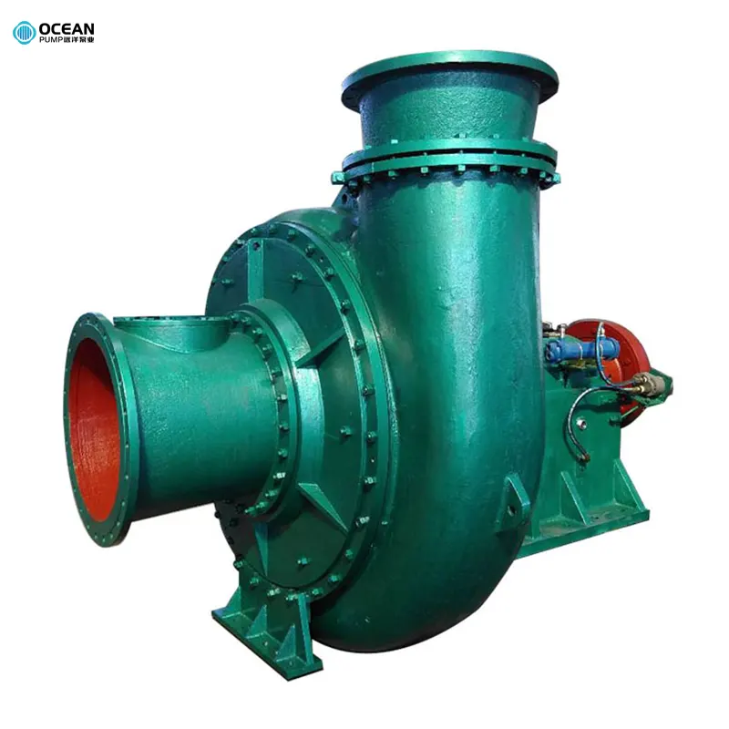
| Discharging Pump (Secondary Pump) | Pressurizes and transports tailings slurry from the buffer pool to the final discharge point (e.g., tailings pond, treatment station) | Centrifugal pumps (PNS or ZS series) | Wear-resistant alloy, ceramic coating |
(B) Working Process
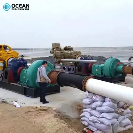
1.Pumping Stage:
The pumping pump is installed at the bottom of the deep pit or near the liquid level. It generates suction through the rotation of the impeller, lifting the tailings slurry along the vertical pipeline to the ground buffer pool (or directly into the inlet of the discharging pump). This stage focuses on solving the problems of "low-level suction" and "anti-clogging", and the pump body is usually equipped with a cutting impeller or large-channel design.
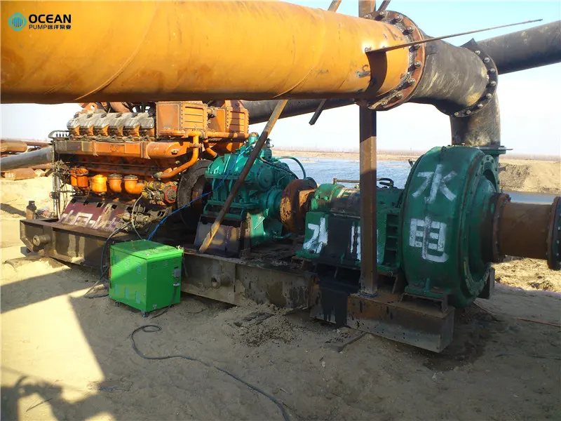
2.Discharging Stage:
The discharging pump sucks the tailings slurry from the buffer pool (or directly from the outlet of the pumping pump) and transports the slurry to a discharge point several kilometers away through higher head pressurization. This stage requires stable pressure to avoid pipeline leakage or slurry deposition.
(C) Key Points of Series Connection Technology
- Head matching: The head of the submersible sand pump must meet the deep pit depth requirement (e.g., if the pit depth is 50 meters, the head should be >= 60 meters), and the head of the discharging pump must cover the transportation distance and height difference (e.g., horizontal distance of 1000 meters + vertical height of 20 meters, head should be >= 30 meters).
- Flow rate synchronization: The flow rates of the two pumps must be matched (error <= 10%) to avoid overflow or idling of the buffer pool, which can be adjusted by a frequency converter.
- Protection devices: Pressure sensors and liquid level switches are set to automatically stop the machine when the liquid level at the inlet of the pumping pump is too low or the pressure at the outlet of the discharging pump exceeds the limit, preventing dry burning or pipe explosion.
III. Advantages of the Dual-Pump Combination System
Improved discharge efficiency:
- Compared with a single pump, the series connection of dual pumps can double the head, meeting the discharge requirements for ultra-deep pits (e.g., over 100 meters).
- Strong continuous operation capability: when one pump fails, the other can temporarily maintain low-load operation, reducing downtime losses.
Reduced equipment wear:
- The pumping pump focuses on "low-head large-flow" extraction, and the discharging pump focuses on "high-head stable transportation", with clear division of labor to reduce overload wear of a single pump.
- The buffer pool can precipitate some large-particle impurities, reducing the clogging risk of the discharging pump.
Flexibility and adaptability:
- The pump model combination can be flexibly adjusted according to the pit depth and transportation distance (e.g., selecting a large-flow slurry pump for the pumping pump and a high-head centrifugal pump for the discharging pump).
- Supports modular expansion: when the mining depth increases, only the discharging pump with a higher head needs to be replaced.
IV. Typical Application Scenarios and Cases
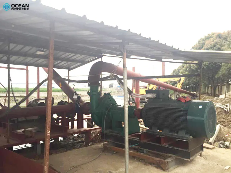
- Tailings discharge in metal mines: In a copper mine with a deep pit depth of 80 meters, the combination of "6/4D-AH slurry pump (pumping) + 8SP-A centrifugal pump (discharging)" is used, with a daily treatment of 5,000 cubic meters of tailings slurry, and the operation failure rate is reduced by 60% compared with the single-pump system.
- Filling mining in coal mines: Tailings slurry is mixed with cement slurry and transported to goaf for filling through a dual-pump system, which not only solves the discharge problem but also realizes mine ecological restoration.
V. Extended Thinking: Optimization Directions for the Dual-Pump System
- 1.Intelligent control: Introduce a PLC automatic control system to adjust the rotation speed of the two pumps in real time according to the tailings concentration and liquid level, achieving energy-saving operation (energy consumption can be reduced by 15%-20%).
- 2.Upgrading of wear-resistant technology: Use new materials such as tungsten carbide-coated impellers and ceramic pump casings to extend the pump life to more than 8,000 hours.
- 3.Environmentally friendly integrated design: Link the dual-pump system with tailings dewatering equipment to achieve integrated "pumping-dewatering-dry stacking" and reduce wastewater discharge.
VI. Equipment Selection and System Configuration for Submersible Sand Pumps and Booster Stations
(A) Submersible Sand Pump Selection
Key Parameters:
- Flow Rate (Q): Based on slurry volume requirements (e.g., 50-2000 m³/h for construction sites).
- Head (H): Sufficient to lift slurry from the suction point to the booster station (e.g., 10-30 m).
- Solid Handling Capacity: Ensure the submersible sand pump can handle slurry particle sizes (e.g., <= 5 mm for fine sand, <= 20 mm for coarse particles).
- Power Rating: Match voltage (e.g., 380V/50Hz) and motor power (e.g., 7.5-30 kW) to site requirements.
Material Considerations:
Choose abrasion-resistant materials (e.g., high-chromium steel impeller, cast iron casing) for prolonged service life in abrasive slurry.
(B) Booster Pump Station Setup
System Components:
- Booster Pumps: Centrifugal pumps with higher heads (e.g., 50-100 m) to overcome long-distance discharge resistance.
- Pressure Vessels & Piping: Stainless steel or rubber-lined pipes rated for high pressure (e.g., PN16-PN25).
- Control Panel: Includes variable frequency drives (VFDs) for speed regulation, pressure sensors, and emergency stop buttons.
- Layout Design: Position the booster station as close as possible to the submersible pump to minimize suction losses, with a height difference <= 5 m to avoid cavitation.
VII. Installation Process
(A) Submersible Pump Installation
Suction System Preparation:
- Suction Pipe: Use rigid pipes (e.g., galvanized steel or PVC) with a diameter 10-20% larger than the pump inlet to reduce friction (e.g., DN80 pipe for a DN65 inlet).
- Strainer: Install a basket strainer at the suction end to prevent large debris (e.g., rocks, wood) from entering the pump.
- Submersion Depth: Ensure the pump is submerged at least 0.5-1 m below the slurry surface to prevent air ingestion; maximum depth <= 20 m for most models.
Electrical Connection:
- Use waterproof cable glands and grounded wiring in compliance with local electrical codes (e.g., IP68-rated cables).
- Install a leakage protector and overload relay in the power circuit to prevent short circuits or motor burnout.
Discharge Pipe Connection:
- Connect the pump outlet to the booster station inlet using flexible hoses (e.g., rubber or steel braided) to absorb vibrations.
- Install a check valve near the pump outlet to prevent backflow when the system is shut down.
(B) Booster Pump Station Installation
Foundation & Anchoring:
- Mount booster pumps on a concrete foundation (thickness >=200 mm) with anti-vibration pads to reduce noise and structural stress.
- Align pump shafts precisely to avoid mechanical damage from misalignment.
Piping Network:
- Design the discharge pipeline with minimal bends ( <= 30¡ã angles) to reduce pressure loss; use expansion joints for thermal compensation in long pipelines.
- Install pressure gauges at the inlet and outlet of the booster pumps to monitor operational parameters.
Control System Setup:
- Program the PLC (Programmable Logic Controller) to interlock the submersible pump and booster pumps: start the submersible pump first, then activate booster pumps once suction pressure stabilizes (e.g., >=0.1 MPa).
VIII. Operational Procedures
(A) Pre-Startup Checks
Submersible Pump:
- Inspect the pump for mechanical damage (e.g., cracked casing, loose impeller).
- Check oil level in the motor chamber (if applicable) and ensure no water ingress.
Booster Station:
- Verify that all valves (suction, discharge, bypass) are in the correct position (suction valve open, discharge valve partially open to prevent high starting current).
- Prime the booster pumps manually if they are not self-priming (e.g., using a water tank or vacuum pump).
(B) Startup Sequence
Start Submersible Pump:
- Power on the submersible pump and monitor current draw (should stabilize within 10-15 seconds).
- Check slurry flow at the discharge pipe; if no flow occurs within 30 seconds, stop the pump to inspect for blockages or air leaks.
Activate Booster Pumps:
- Once the submersible pump achieves steady flow (e.g., 3-5 minutes), start the booster pumps one by one (with a 10-second interval between units in a multi-pump station).
- Adjust the discharge pressure via VFDs to the required level (e.g., 0.6-1.0 MPa for 500 m discharge distance).
(C) Normal Operation Monitoring
Key Parameters:
- Submersible Pump: Current ( <= 90% of rated current), motor temperature ( <= 75 C), suction pressure (>=-0.05 MPa to avoid cavitation).
- Booster Station: Discharge pressure (maintain within 10% of setpoint), pump vibration ( <= 5.0 mm/s), and oil temperature ( <= 60¡ãC for gearboxes).
Regular Checks:
- Inspect pipes for leaks or abrasion (especially at bends and flanges).
- Monitor slurry density: if solids content exceeds 60% (by weight), reduce flow rate to prevent pump overload.
(D) Shutdown Sequence
- 1.Reduce booster pump speed via VFDs to minimum (e.g., 20 Hz) to lower discharge pressure.
- 2.Stop the booster pumps, then shut off the submersible pump after 1-2 minutes to clear the pipeline of residual slurry.
- 3.Close all valves and drain the pipeline if the system will be idle for extended periods (to prevent slurry sedimentation).
IX. Company Profile: Tai'an OCEAN Pump Co., Ltd.
As a leading manufacturer, supplier, and exporter of sand pumps and sand dredger solutions in China, Tai'an OCEAN Pump Co., Ltd. specializes in providing comprehensive pumping solutions for mining, construction, and environmental engineering.
Core Strengths:
- Over 30 technical experts in sand pump design and application.
- 15,000 m² modern manufacturing facility with advanced production equipment.
- Product portfolio: 4 major series and 20+ types of sand pumps, slurry pumps, sand dredgers, and related components.
Contact Information:
- TAIAN OCEAN PUMP CO.,LTD
- WhatsApp: +86 18562293319
- Email: oc@tsbeng.com
- Address: Tai'an City, Shandong Province, China (271000)
-
WhatsApp
-
E-MailE-Mail:oc@tsbeng.com
-
WeChatWeChat:yychen19


